Upgrading Sovol SO-1 Pen Plotter to BigTreeTech SKR-2 32 Bit Controller Board with TMC2208 Stepper Motor Drivers and Marlin 2.0 Firmware

I decided to upgrade the controller board on my Sovol SO-1 pen plotter for a few reasons. First, the controller board that comes with Sovol SO-1 is not currently available to purchase separately in case it should break and Sovol doesn't seem to be even selling Sovol SO-1 device anymore just the SO-2 model, so I don't think the controller board part will ever be available for sale in the future. Second, the original board has A4988 stepper motor drivers and has an 8 bit controller so it is relatively loud when moving at slower speeds. Third, the firmware for the stock controller was released on the Facebook group for Sovol plotters but it is the compiled firmware that was released, not the Marlin files that would allow any changes to be made and recompiled myself, and I wanted to be able to experiment with Marlin 2 and see if the drawing quality would change.
This is what I used for the switch, and I purchased 3/16 inch spade connectors to connect to the switch. I undersized the rectangular opening in the enclosure by 1-2 mm, rather than modify model and reprinting it I used a Dremel with a drill bit to widen opening slightly.
I chose Big Tree Tech SKR-2 board to be the replacement, which currently is 50 dollars on amazon, I think I paid about 40 dollars at the time I purchased it. The current model of SKR-2 comes with F429 chip which has a maximum speed of 180MHz, compared with the stock board's Atmega1284p which has a 20MHz maximum speed. In addition, the SKR-2 is 32 bit versus 8 bit on the stock controller. SKR-2 has sockets for its stepper motor drivers so if I burn out a stepper motor driver I can just replace it without having to replace the entire board.
I also purchased Big Tree Tech (BTT) TMC2208 V3 drivers which are currently 25 dollars on amazon for 5 (but only need 2 for X and Y, so will have some extras in case of failure), which come with heat sinks. There are some small jumper pin connectors on the board near stepper drivers, I adjusted which ones to leave in place for uart mode per the manual. There are solder pads on the bottom side of the TMC2208 drivers at J2 that have to be bridged to put them in UART mode. I changed the power jumper pin from usb to external power supply.
I initially downloaded the Marlin from BTT SKR-2 GitHub repository. This was my first time using Marlin 2 with Visual Studio Code, previously I have used Arduino software to upload and modify Marlin firmware for other devices such as atmega2560 with ramps 1.4. For SKR-2 with Marlin2 you compile the firmware, transfer that file to an SD card and then put the SD card in the SKR-2 and power it up. I'm not sure what I was doing wrong but after I compiled the software, initially I couldn't get SKR-2 to connect and communicate by USB with my MacBook with either Repetier host or on the terminal with Octoprint. I contacted BTT by email and they suggested to try BIQU-B1 printer repository Marlin firmware (https://github.com/bigtreetech/BIQU-B1) as the starting point (which is based on SKR-2 board), now I was able to communicate with it using terminal of Octoprint via my raspberry pi 3b with USB (but still not repetier host for unclear reasons).
Next, I made some various changes to BIQU-B1 Configuration.h and Configuration.adv files. I was able to get rid of extruder. If you are wondering why there is a Z axis included, I couldn't get it to compile without leaving Z in the marlin firmware.
I will try to document what I changed as follows (hopefully I didn't miss anything). Note, I am not using any LCD with the plotter now, I just use Octoprint interface on my laptop. Towards the bottom of this blog entry, you will be able to download my adjusted version of Marlin for Sovol SO-1 using SKR-2.
In configuration.h some of the settings I changed while doing this:
#define CUSTOM_MACHINE_NAME "Sovol SO-1 SKR2F429 Kevin Lease"
This is where I set the name of the machine.
//#define EXTRUDERS 1
#define EXTRUDERS 0
Don't need an extruder for a pen plotter.
//#define TEMP_SENSOR_0 1
#define TEMP_SENSOR_0 0
I don't need a temperature sensor on an extruder.
//#define TEMP_SENSOR_BED 1
#define TEMP_SENSOR_BED 0
I don't have a heated bed so I don't need a temperature sensor on a heated bed.
#define USE_XMIN_PLUG
#define USE_YMIN_PLUG
#define USE_ZMIN_PLUG
These settings are for limit switches. Not that I don't actually have any physical Z limit switch but Z axis had to be included in the Marlin firmware for me to get it to compile.
#define ENDSTOPPULLUPS
This may not be necessary, but I included it. The end stops have only two wires. I wired my end stop connectors to connect to the signal and ground pins on the 3 pin endstop socket on the SKR2 board and left the 5V unconnected.
#define X_MIN_ENDSTOP_INVERTING false // Set to true to invert the logic of the endstop.
#define Y_MIN_ENDSTOP_INVERTING false // Set to true to invert the logic of the endstop.
#define Z_MIN_ENDSTOP_INVERTING false
If the X or Y end stop reads triggered when in open state with M119, the endstop settings here can be switched from false to true. If the wiring connection is faulty it will also read as triggered. Z will read as triggered due to no physical endstop, I ignore that.
#define X_DRIVER_TYPE TMC2208
#define Y_DRIVER_TYPE TMC2208
#define Z_DRIVER_TYPE TMC2208
I used TMC2208 drivers
#define DEFAULT_AXIS_STEPS_PER_UNIT { 160, 160, 400 }
Since I increased my microsteps (see below on configuration_adv.h) from 16 to 32 on X and Y, I multiplied the steps per unit by 2 (i.e. 80 x 2 = 160). I left Z at 400, not using Z axis so it doesn't matter. I removed the 96 present originally as the fourth axis which would have been the steps for the extruder since I have no extruder.
//#define DEFAULT_MAX_FEEDRATE { 150, 150, 5, 25 }
#define DEFAULT_MAX_FEEDRATE { 150, 150, 5 }
I removed extruder default max feedrate
//#define DEFAULT_MAX_ACCELERATION { 1000, 1000, 100, 10000 }
#define DEFAULT_MAX_ACCELERATION { 1000, 1000, 100 }
I removed extruder default max acceleration
//changed from 500 to 1000 for next three
#define DEFAULT_ACCELERATION 1000 // X, Y, Z and E acceleration for printing moves
#define DEFAULT_RETRACT_ACCELERATION 1000 // E acceleration for retracts
#define DEFAULT_TRAVEL_ACCELERATION 1000 // X, Y, Z acceleration for travel (non printing) moves
changed default acceleration from 500 to 1000
#define CLASSIC_JERK
#if ENABLED(CLASSIC_JERK)
#define DEFAULT_XJERK 5.0
#define DEFAULT_YJERK 5.0
#define DEFAULT_ZJERK 0.3
Removed comment marks to define classic jerk.
//commented out bltouch
//#define BLTOUCH
I have no bltouch, I am going to use socket for bltouch servo for the pen plotter servo instead.
#define INVERT_X_DIR false
#define INVERT_Y_DIR false
#define INVERT_Z_DIR false
The X and Y be changed to true if axes move the wrong direction depending on wiring stepper motor.
#define X_HOME_DIR -1
#define Y_HOME_DIR -1
#define Z_HOME_DIR -1
#define X_BED_SIZE 235
#define Y_BED_SIZE 335
#define X_MIN_POS 0
#define Y_MIN_POS 0
#define Z_MIN_POS 0
#define X_MAX_POS X_BED_SIZE
#define Y_MAX_POS Y_BED_SIZE
#define Z_MAX_POS 270
#define NUM_SERVOS 1 // Note: Servo index starts with 0 for M280-M282 commands
Need to have one servo so I can move pen up and down.
//was 300 for servo_delay
#define SERVO_DELAY { 5 }
The delay was arbitrarily decreased from 300ms to 5ms, as I will use dwell command G4 in my gcode to allow a delay after each servo move.
Configuration_adv.h:
//#define AXIS_RELATIVE_MODES { false, false, false, false }
#define AXIS_RELATIVE_MODES { false, false, false }
I removed fourth false due to no extruder.
#if AXIS_IS_TMC(X)
#define X_CURRENT 570 // (mA) RMS current. Multiply by 1.414 for peak current.
#define X_CURRENT_HOME 570 // (mA) RMS current for sensorless homing
// was 16
#define X_MICROSTEPS 32 // 0..256
#define X_RSENSE 0.11
#define X_CHAIN_POS -1 // -1..0: Not chained. 1: MCU MOSI connected. 2: Next in chain, ...
//#define X_INTERPOLATE true // Enable to override 'INTERPOLATE' for the X axis
#endif
Decreased root mean square current to 570mA from 800mA on X and Y. The steppers are nema17, 42mmx42mmx34mm. I think they are the same steppers that creality uses on Z axes. These are 1.8 degrees per step, in other words 200 steps per revolution. I changed the microsteps from 16 to 32 on X and Y. I noticed previously with the stock controller board that the steppers would get pretty hot after making a drawing. I will look to see if stepper motors will run cooler with my setup.
#if AXIS_IS_TMC(Y)
#define Y_CURRENT 570
#define Y_CURRENT_HOME 570
// was 16
#define Y_MICROSTEPS 32
#define Y_RSENSE 0.11
#define Y_CHAIN_POS -1
//#define Y_INTERPOLATE true
#endif
 |
| location of single jumper pin for X and Y stepper drivers on SKR-2 using BTT tmc2208 V3 drivers in UART mode |
 |
Underside of BTT TMC 2208 V3 stepper driver. I made a solder bridge across all 3 pads of J2 for UART mode (this image is before soldering) After I made an adjustment to the Marlin firmware and uploaded to SD card and rebooted SKR-2, I connect to SKR-2 via octoprint, and I used M502 and then M500 commands via octoprint terminal to make the EEPROM take the changes I made in the firmware. |
I designed my own enclosure in Fusion360 for the SKR-2. I used several models created by others on grabcad to help me with my design (an SKR2 model by Phil Maddox, a Noctua 40mm fan model by Stephan Bolvin and a Noctua 80mm fan model by John). For cooling, there are heat sinks on the TMC2208 drivers and a 14x14mm one placed on F429 chip, two Noctua 40mmx40mmx 10mm fans that move air over the stepper drivers and the F429 chip and an 80mmx 80x 25mm noctua fan on top to vent the entire enclosure. These noctua fans are so quiet that it's difficult for me to tell when they are running by sound. Hopefully, the extra expense of the cooling fans will help keep the board and drivers running trouble-free for a long time. The 40mm fans are powered by plugging into always on fan sockets on the board. The 80mm fan is powered by the 12V power where the supply enters the enclosure. 12VDC power comes in on the left side and there is a cable restraint to keep it from slipping that is held in place with several screws and a switch to control power. There are tabs on the sides to allow 6mm screws to securely mount the enclosure on mdf with threaded inserts installed from the underside. There is a small shelf on the right inner wall to restrain entering stepper motor, endstop and servo wires with zipties. There are some pieces on the inside that are custom wire guides for cable management purposes. The design makes use of square captured nuts (use change filament at layer in Cura to pause at desired levels, uxcell 6mm and 10mm long M3 screws and honbay square nuts accepting 3mm screws from Amazon to assemble parts. With my printer tolerances and printing with PLA, when I make a space for these honbay square nuts to be captured in a print, I make the squares 5.5mm on X and Y and use 2.6mm for height, and I model the hole sizes to be 3.7mm. I usually apply a tiny bit of ca glue on an edge of the nut after placing it then dab up excess with a cotton tip applicator, to make sure the nut won't move. Cura custom supports were used for rectangular openings in enclosure. The USB access to the board and SD card access are on the front face of the enclosure.
 |
| External appearance of enclosure in Fusion360 |
 |
I had a 12V power supply on hand. I crimped ferrules on the ends of wires going to the SKR-2 power supply terminals.


 |
| Internal view of SKR-2 enclosure in Fusion360 |
I removed the stock board and LCD, and made extension cables with JST XH 2.5mm connectors on silicone ribbon cables from aliexpress, these will run along MDF surface parallel to Y axis aluminum extrusion, pass through back piece and then head left over to the controller board in back left. I created a 3d printed rectangular piece to mount on the internal standoffs of stock enclosure, but it didn't quite clear the back piece of metal when reassembled so I just cut it back a bit with a saw. I superglued a piece of top of this to use as base (has embedded nuts for 3mm screws) to restrain the silicone cables with 3d printed piece that clamps over the ribbons.
 |
| front view of SKR2 enclosure |
I usually use cctree brand pla filament, which is normally great. There were a couple of colors of cctree PLA on sale on Amazon that were discounted about 5 dollars off per roll, this was silver. Unfortunately, I suspect it was old filament inventory that they were trying to get rid of because it had a tendency to snap and didn't give as good of interlayer adhesion as normally I would get with other cctree I have used.
 |
| This is the design to put a ribbon cable mount inside the stock metal enclosure after removing the original board and LCD. |
 |
| The printed piece was hitting the metal back wall of the enclosure, I could have redesigned it and reprinted, but I just cut a piece out with a small saw, reprinted small area of ribbon cable mounting and used ca glue to attach. |
 |
| Inside stock controller board enclosure with ribbon cable extensions instead of the controller. |
 |
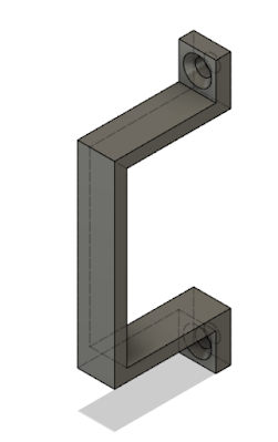
| I changed the 3d printed bracket at the opposite end of the Y axis to allow pass through ribbon cable wires |
I made rectangular and circular 3d printed pieces to fill in gaps on the front of the metal enclosure where the LCD and knob had been and superglued them to the back of the 3d printed rectangle spanning the inside the stock enclosure.
 |
| My SKR2 Enclosure with everything installed inside |
 |
| Another slightly different view |
 |
| Underside view of lid of skr2 enclosure |
 |
| this is the 12V power supply I am using |
 |
Next steps will be testing it out and tweaking settings more. First, I need to mount all the parts on the MDF supports, I used inserts and m6 screws from McMaster-carr for this purpose.

 |
| This is the threaded support I use in MDF and the hex driver. |
 |
| Marking drill marks for ribbon cable holder |

 |
Back of MDF support after adding additional threaded inserts for mounting SKR2 enclosure, 12V power supply, raspberry pi, surge protector power strip and ribbon cable restraint |
 |
| Surge protector power supply mount |
 |
| Fusion 360 model of mounting bracket for my 12V power supply (two printed), I put a piece of black eva craft foam between the bracket and the power supply because I made the vertical legs about 1mm too tall. |


 |
| Surge protector I purchased from ace hardware. |
 |
| Fusion360 model of Raspberry pi mounting bracket fits over the acrylic case that came with the used pi I bought on eBay, I used ca glue to attach it to the top of the case. |
 |
| Ribbon cable restraint |

Installed on MDF
 |
| Repeated shim process to level SO-1 and reinstalled SO-1 on MDF support |
I will place the files on my google drive in a folder to share.
Using octoprint, I jogged around and homed the Sovol SO-1 pen plotter, moved the servo for the pen up and down. It's very quiet compared to stock controller, as expected. The next step will be further testing of this new setup.
Disclaimer
The author does not make any warranties about the completeness, reliability and accuracy of this information. Any action you take upon the information on this site is strictly at your own risk, and the author will not be held liable for any losses and damages in connection with the use of this information.

This work is licensed under a Creative Commons Attribution-NonCommercial-ShareAlike 4.0 International License.

Hello, you make a great work with this moddification! I made it too, with your described instructions. But I want to make a faster drawing and writing. What I must change to do this? I'm not fammiliar with 3D printing and Marlin software, this is my first touch to this, and doesend understand all instructions from second blog post. Many thanks in advance. Best regards, Alex.
ReplyDelete